PROTOTYPE STAGE IV—THE EXPLORATION OF FEET PLATFORM

photo-08-11-2016-17-37-49%e5%89%af%e6%9c%ac

photo-11-11-2016-15-32-23%e5%89%af%e6%9c%ac

The feet platform is a very imporatant part, as the direct tangible interface for users to control. Its accuracy strongly related the ball movement on the physical sheets.

The reason why they are strongly related because the adxl345 (accelerometer sensor) is horizontal inserted into the bottom part the feet playform surface, in order to get the accurate data of users’ feet movement.

After a series of testing, I chose the 360 degree ball head to make the movement smmoth, and easy to use for the users, and finally use the velcro to secure.

DSC04428副本.jpgDSC04455副本.jpg

PROTOTYPE STAGE IV—THE EXPLORATION OF STEP MOTOR

After I done the mechanical part of modeling, I use the servo to try it again in order to make sure it works good enough for the users’ control. And Itried it many times,I suffered from another mechanical issue, this time the servo is powerful enough to drive the whole physcial model.

However, the servo cannot drive the physical model move as a enough slope,I cannot find the reasons and then I discussed with Gareth, which aims to find the solution. Finally, I found due to the servo just works for 180 degrees, and this is not enough to drive the physical sheets to finish the game process.

111.jpg

屏幕快照 2016-11-29 上午9.35.26.png

Then I followed the Gareth and Tom’s advice, using the step motor to drive it because the step motor can drive in cyclic 360 degrees. Also fot the noise problem of the adxl345, Yoogle helped me to switch a little of the code and then it works between than before. Throughout these issues I have suffered, I found that when the menchanical system work together the digital system, it is super complex, and easy to encounter problems, sometimes the practice push you back to research, and I believe this is the key of critical design thinking, reserach through practice.

屏幕快照 2017-01-06 下午11.25.55.png

PROTOTYPE STAGE III—PHYSICAL MODELING & THE MECHANCIAL WORKING PRINCIPLE

Then I started to build the physcial part of my project, the game routine is inspired by the basketball tactics, triangle offense’s movement, what I have explained in the research stage. My game procedure consists of serval triangles, which mirrors the real movement in the basketball game. I designed it in AI software, the whole piece contains serval parts, and I cut them separately and construct these 2D things into a 3D model by using some super glues.

屏幕快照 2017-01-06 下午11.14.51.png

Photo 04-11-2016, 14 38 28.jpg

Another point was mentioning is the bottom part, it is the most crucial part of the whole physical piece. It based on the lever principle, works in mechancial and digital principle at the same time. Firstly, when the servo receive the order from the adxl345 and arduino, servo will rotate in the same degrees, and then the pulley on the servo will drive the belt. Once the belt is drived, it will connect the two pulleys work together at the same time. Then the pulleys drive the stick, and finally the stick will pull the two springs through the strings, leading to the movement of the whole physcial piece.

Photo 29-11-2016, 09 02 57.jpg

Photo 19-11-2016, 17 47 48.jpg

Photo 09-11-2016, 16 20 46.jpg 副本.jpg

PROTOTYPE STAGE III—EXPERIMENTS OF THE STRECHING RUBBER SENSOR

Although the new servo had worked with the adxl345 sensor, it still contains some risks, that is the noise from different direction. This means that because the adxl345 is based on the X,Y,Z, so when you rotate the sensor not competely in one direction, the noise from other direction movement will influence the transmission of the signal. Leading to the fact that the servo will receive the inaccuracy order, and shaking for few seconds, this makes me very struggle and hard to fix.

Low_Pass_Alpha_Point_One.png

technique.jpg
The testing of adxl345’s noise influence

Then I discussed with Gareth again, he suggested me to use the stretching rubber sensor to do the test. Due to the good extensibility of it, it is easier to drive my physical feet platform. However,unfortunately, the stretching sensor also work along with some noise, influence the rotating of the servo, even more worse than the adxl345.

屏幕快照 2016-11-29 上午8.03.53.png

屏幕快照 2016-11-29 上午8.11.19.png

屏幕快照 2017-01-06 下午11.05.50.png

屏幕快照 2017-01-06 下午11.08.36.png     Test the noise of the stretching rubber sensor

The reasons why the stretching sensor along with more noise,  after many times tseting, I found it is because Static electricity of our body or the air make the sensor instable.

PROTOTYPE STAGE III—EXPERIMENTS OF THE DIFFERENT KINDS OF SERVO MOTOR

SER1.jpg

屏幕快照 2016-11-29 上午7.41.49.png

After researching the reference of the servo, I started my first experiment with the MG996R sensor. For the coding, I encountered some issues, the different orders of the servo and the accelerometer sensor fight with each other on the “serial print” step, leading to the fact that I cannot upload the code to the arduino and control the servo. This is a big difficulty for me and even Gareth cannot fix this problem in few days. Then I tried to discuss with our classmates, finally after five days, with the help of Yoogle and Gareth, I fix it by changing the coding methods.

SC_0252MG_2.jpg

SER2.jpg

屏幕快照 2016-11-29 上午7.42.47.png

At the same time, another issus came to me, because of the MG996 servo has the limition of the driving weight, just 1kg to 2kg, it is not enough for driving my physical installation. Then I switched to SAVOX 0252 servo motor, it is a very good servo and mostly can drive 10.5kg theoretically at most. And it finally worked.

PROTOTYPE STAGE II—THE ANALYSIS AND EXPERIMENTS OF THE SERVO MOTOR

Servo-Motor.jpg

two_servos.png

Throughout reading some online reference and videos, I found that servo motor is basically a DC motor, along with some other special purpose components that make a DC motor a servo. It consists of a small DC motor, a potentiometer, gear arrangement and an intelligent circuitry.

For the connection, most of servos have three circuits, which can be connected with the arduino and controlled by the coding. In three of them, two connects with the 5V because normally it is the power working condition of the servos, whereas another circuit is responsible to communicate with arduino and get the data.

The intelligent circuitry along with the potentiometer makes the servo to rotate according to our coding. Also, I found a small DC motor will rotate with high speed but the torque generated by its rotation will not be enough to move even a light load. The gear mechanism will take high input speed of the motor (fast) and at the output, we will get an output speed which is slower than original input speed but more practical and widely applicable.


PROTOTYPE STAGE II—ANALYSIS OF ADXL345’S WORKING PRINCIPLE

adxl345_to_arduino_uno.png

屏幕快照 2016-11-29 上午6.28.42.png

Connection & Working Principle diagram from “Sparkfun”

After talking about my concpet with Gareth and Nicolas, they suggested me to use the accelerometer sensor to track the feet movement and transfer the data to the arduino, and the arduino with send the order to motors, and the two motors will activated the movement of the physical installation in different directions.

After my research online, I found that the ADXL345 is a small, thin, low power, 3-axis accelerometer with high resolution (13-bit) measurement at up to ±16 g. In addition, the digital output data is formatted as 16-bit twos complement and is accessible through either a SPI (3- or 4-wire) or I2 C digital interface. It is a very sensitive sensor and easy to use, and then I programmed it with arduino and made it basically work first.

In the working principle, it works in four different channels, the GND, VCC SDA and SCL respectively. The GND and VCC supply the power for the accelerometer, at the same time the SDA and SCL responsible for transfering data form X, Y, Z.

屏幕快照 2016-11-29 上午7.00.32.png

屏幕快照 2016-11-29 上午6.26.12.png

Programming after discussing with Gareth

PROTOTYPE STAGE I —USER FLOW SKETCHES A

sk3.jpg

STEP 1

User entry into the space and sit down on the chair, at the same time put the feet on the physical platform and use the velcro to secure.

STEP 2

User start rotating in different four directions and activated the movement of the physcial installation in different angles or slopes.

STEP 3

The different layers of the physical wood box will trigger the movement of the small ball (on the surface), and finally arrive the destination.

CONCEPT BRAINSTORMING

屏幕快照 2017-01-06 下午5.49.14.png

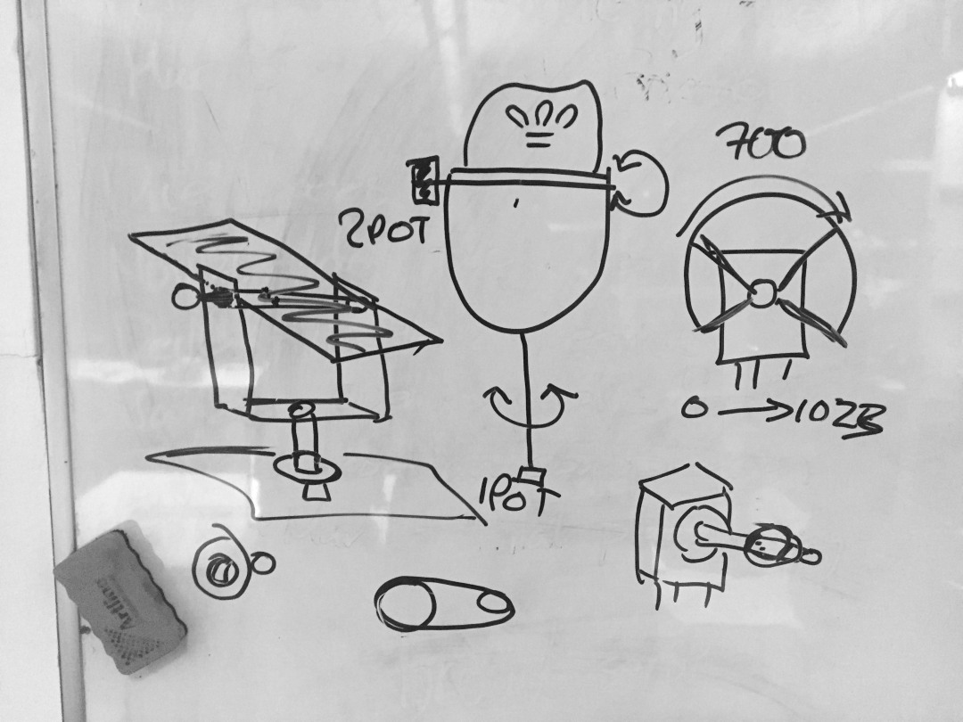
After a lot of research on the feet gestures, tangible interface forms, working principles, and spatial tactic movements, I engaged the concept of the final major project, which uses basic stretching recovery gestures as my project feet gestures. These four simple gestures are rotating front, back, left and right, which responses to the real movement in the basketball game, therefore building a bridge for users in between human feet gestures and the spatial awareness.

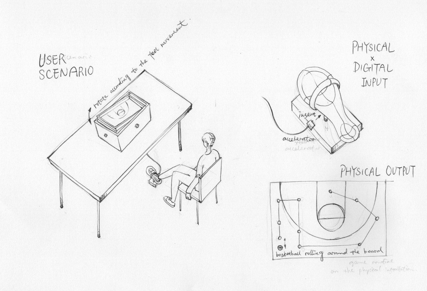
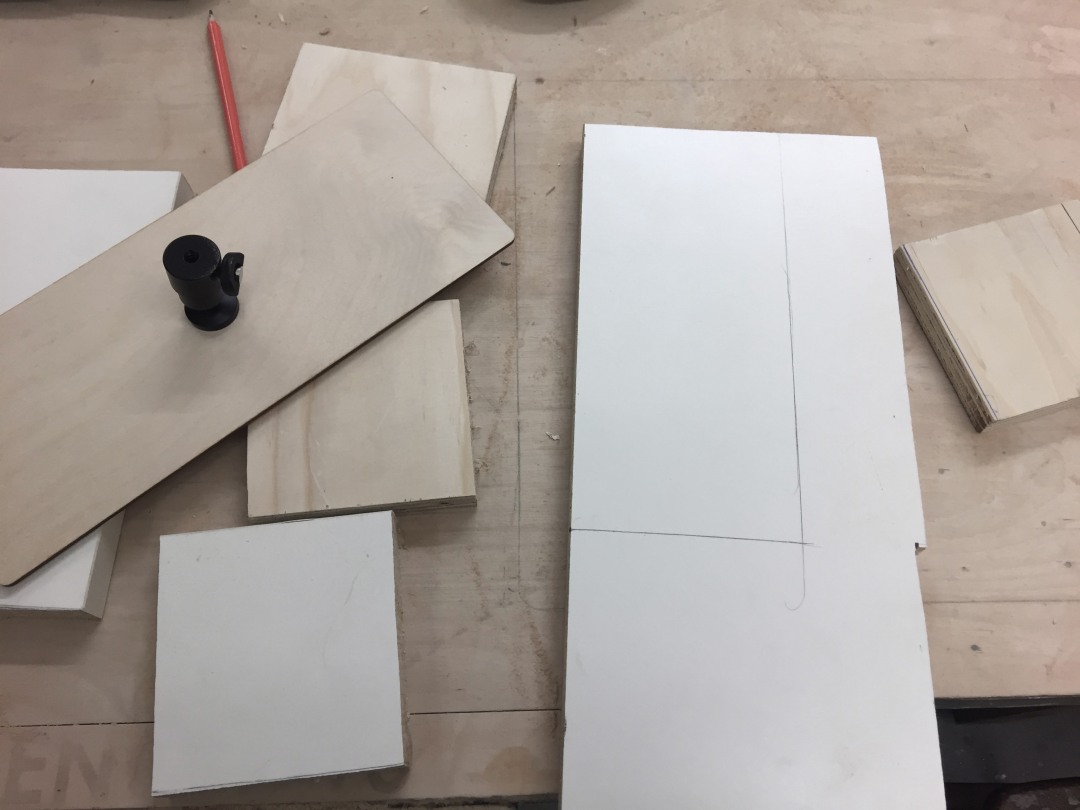
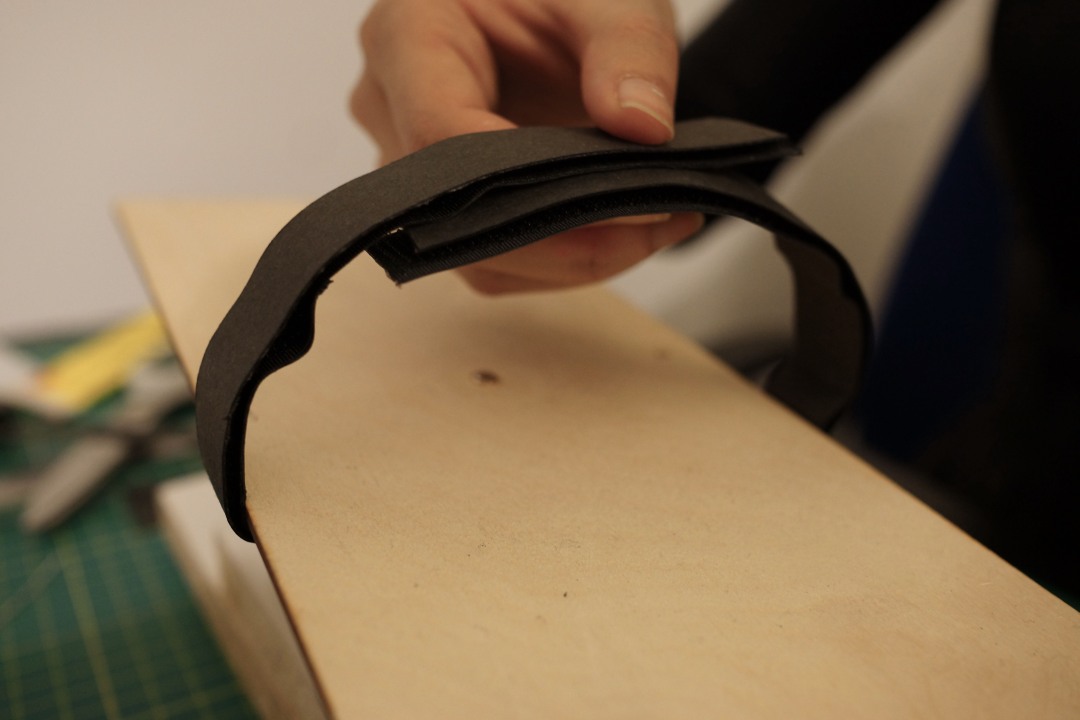
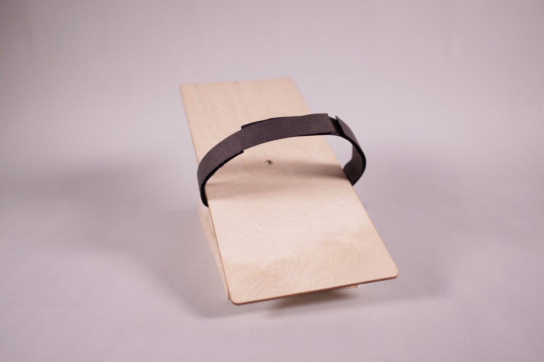
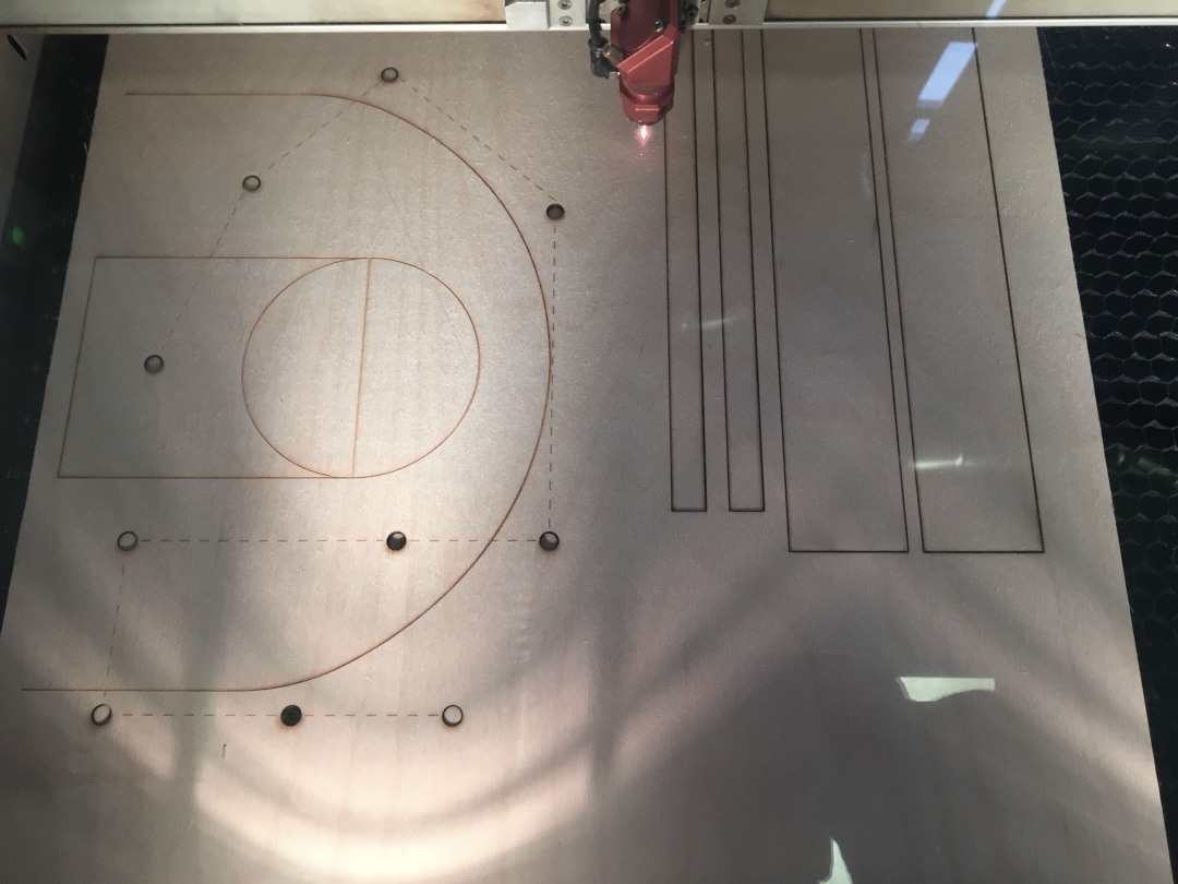
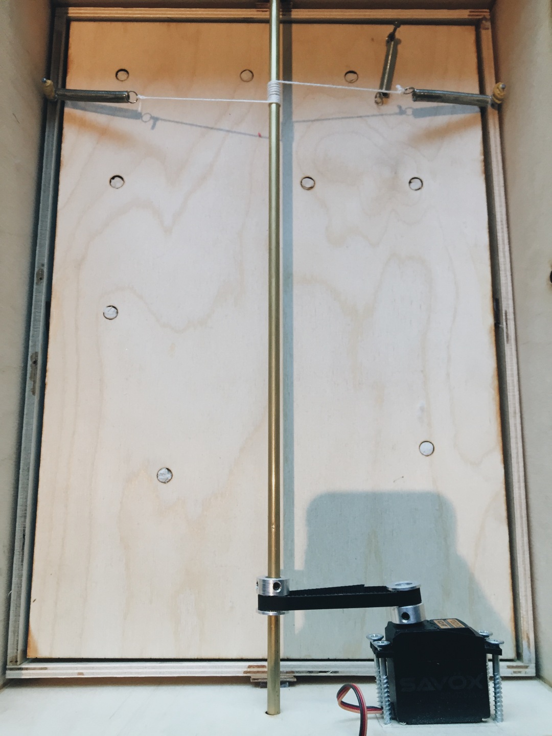
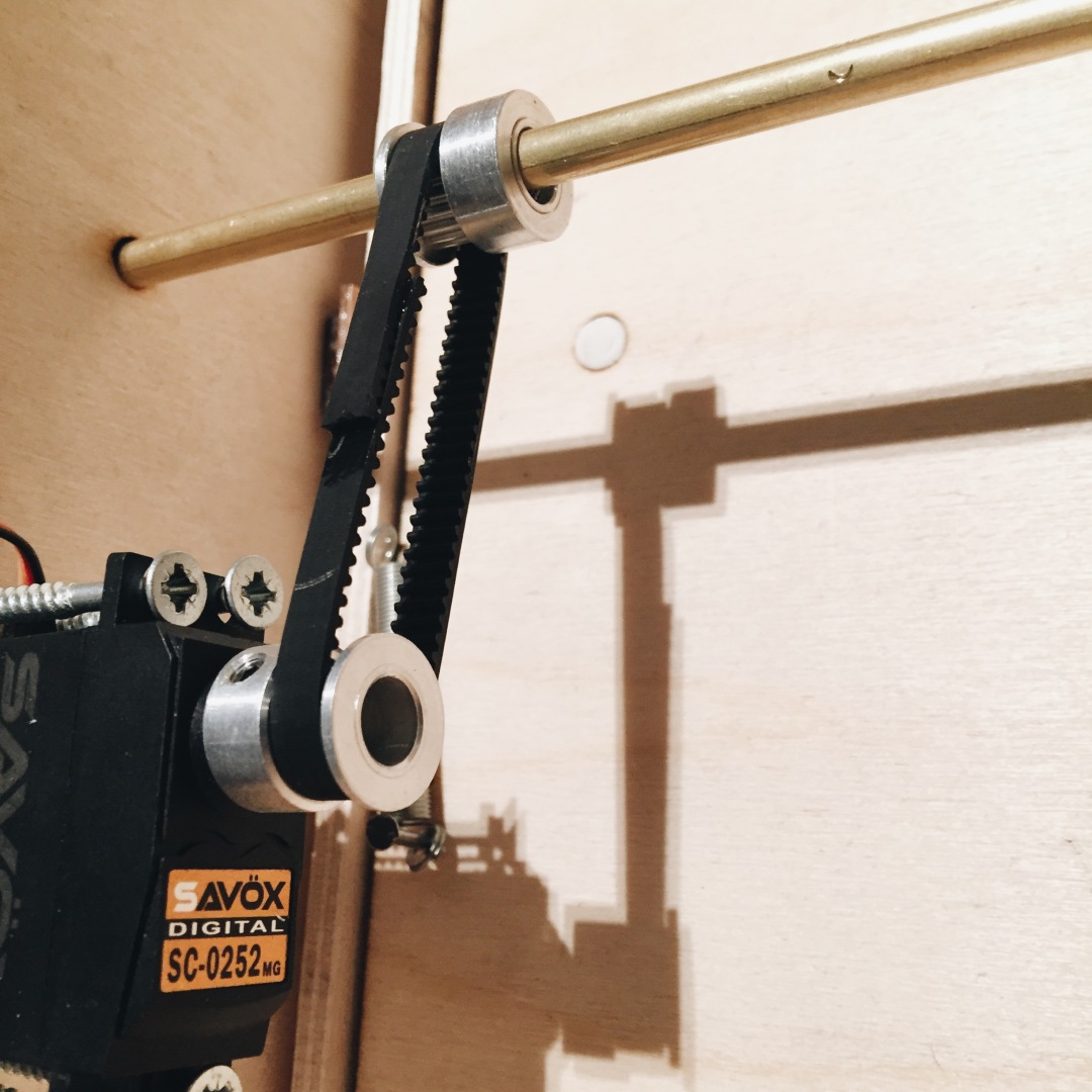
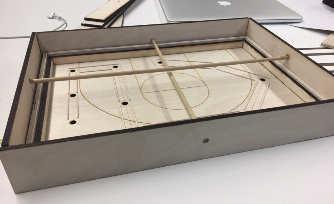
For the movement of user flow of my project, I chose to use a physical interactive interface, that is a wood box which representing a basketball court.In addition, I built a small platform for users to put their feet and control the physical installation. When users put their feet on the platform and rotate in any direction of those four, it will directly control the physical wood sheet as the same slope and the ball will move in this space.

Another point worth mentioning is that users can have a break at any assign point in the flow, this is aimed to consider users from the emotional perspective when they play with it, and to follow the user-friendly design rule.

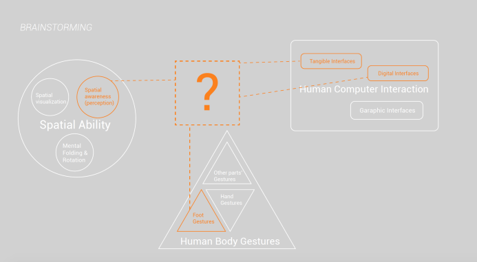
My Project explores the relationship between the human feet guseture and people’s spatial awareness throughout building a amusing game movement of the interactive installation.

The project consists of two parts, the feet platform which for users to control by rotating left, right, backward and forward. Another part is the physcial wood box what is a ball movement game.

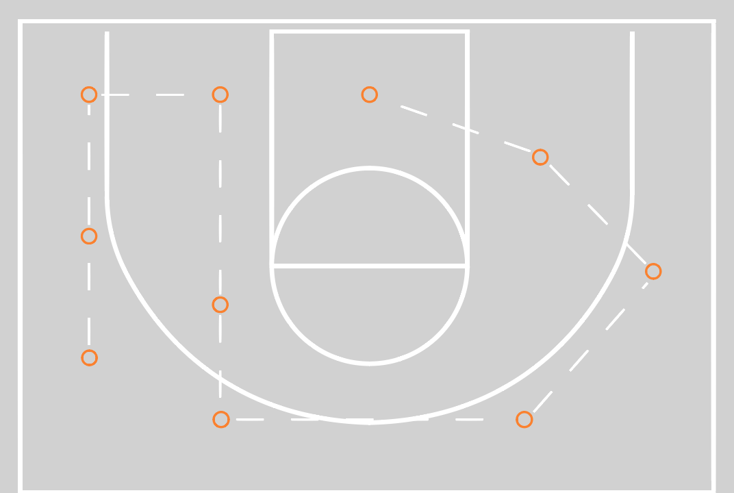
The feet gestures are inspired from the basic streching gestures of the feet injury recovery, and the game procedure is inpired and created by the basketball tactics routine. In my users’ scenario, how the ball go through the path mirrors how the player move in a real basketball game, whcih aims to build a bridge between the Feet gesture and the real movement in a narrative space, and therefore raise users’ Spatial awareness in a enjoyable way.
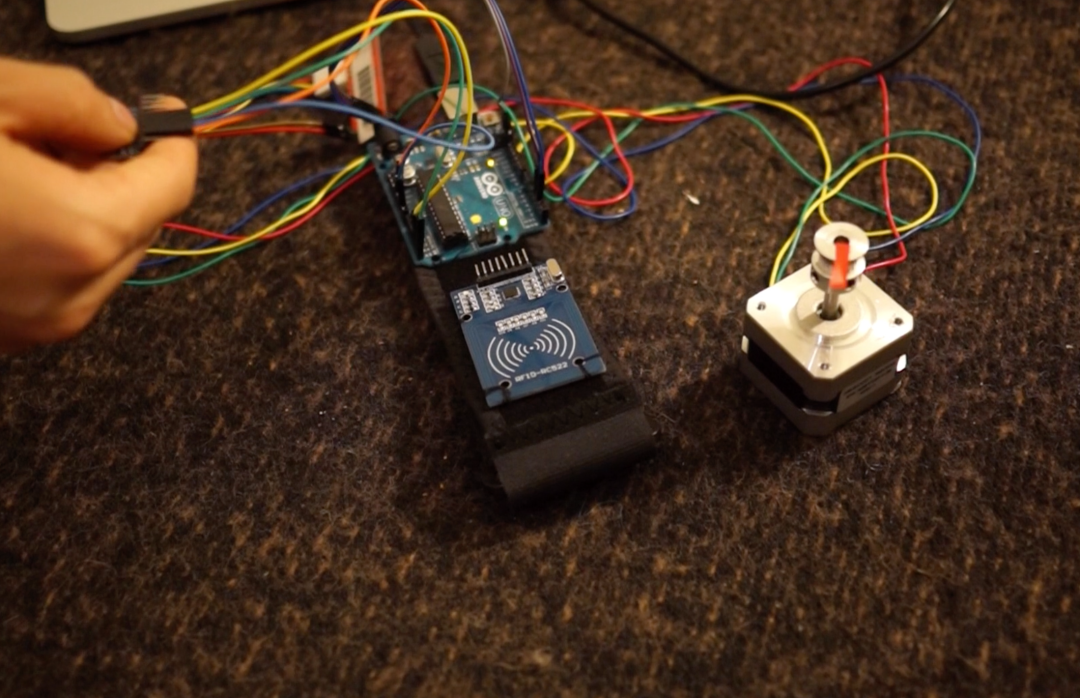
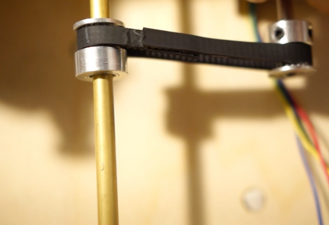
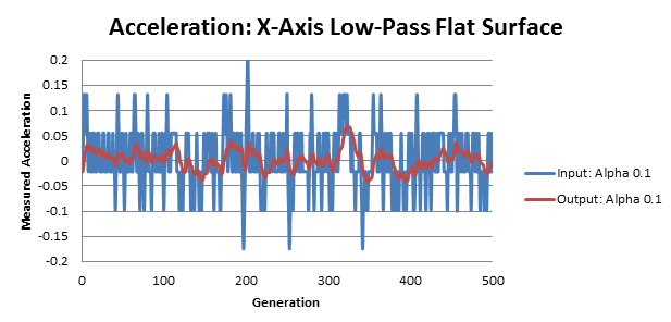
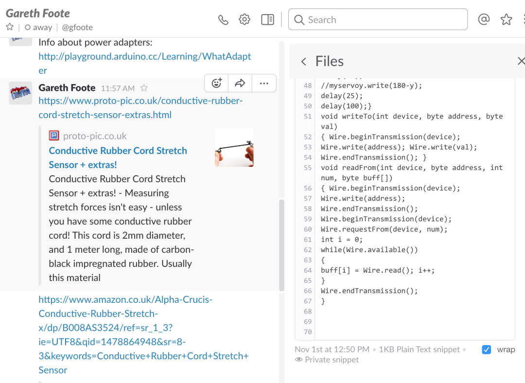
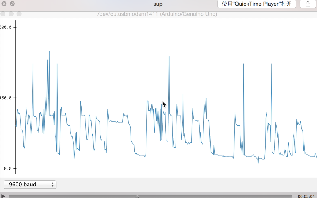
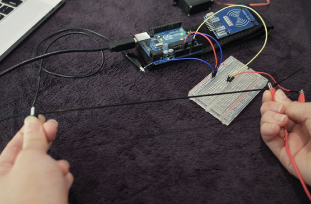